
I bought this cheap shield (currently not being sold on eBay) hoping it was going to work but ended up not working out the box. I used coryjfowler’s MCP_CAN_lib library and stuck with the default CS pin #10 and INT pin #2. Here is an example of working code I used for Martin Vijoen’s CAN-BUS Super Sniffer:
#include <mcp_can.h>
#include <SPI.h>
#define CAN0_INT 2 // Set INT to pin 2
MCP_CAN CAN0(10); // Set CS to pin 10
INT32U canId = 0x000;
unsigned char len = 0;
unsigned char buf[8];
void setup()
{
 Serial.begin(38400);
START_INIT:
 // Initialize MCP2515 running at 16MHz with a baudrate of 500kb/s and the masks and filters disabled.
 while(CAN0.begin(MCP_ANY, CAN_500KBPS, MCP_16MHZ) != CAN_OK){
 Serial.println("Error Initializing MCP2515...");
 delay(1000);
 }
 Serial.println("MCP2515 Initialized Successfully!");
 CAN0.setMode(MCP_NORMAL); // Set operation mode to normal so the MCP2515 sends acks to received data.
 pinMode(CAN0_INT, INPUT); // Configuring pin for /INT input
 Serial.println("MCP2515 Library Receive Example...");
}
void loop()
{
 if(!digitalRead(CAN0_INT))
 {
 CAN0.readMsgBuf(&canId, &len, buf);
 Serial.print("<");
 Serial.print(canId);
 Serial.print(",");
 for(int i = 0; i < len; i++)
 {
 Serial.print(buf[i]);
 if (i != (len - 1) )
 Serial.print(",");
 }
 Serial.print(">");
 Serial.println();
 }
}
What I had to do physically:
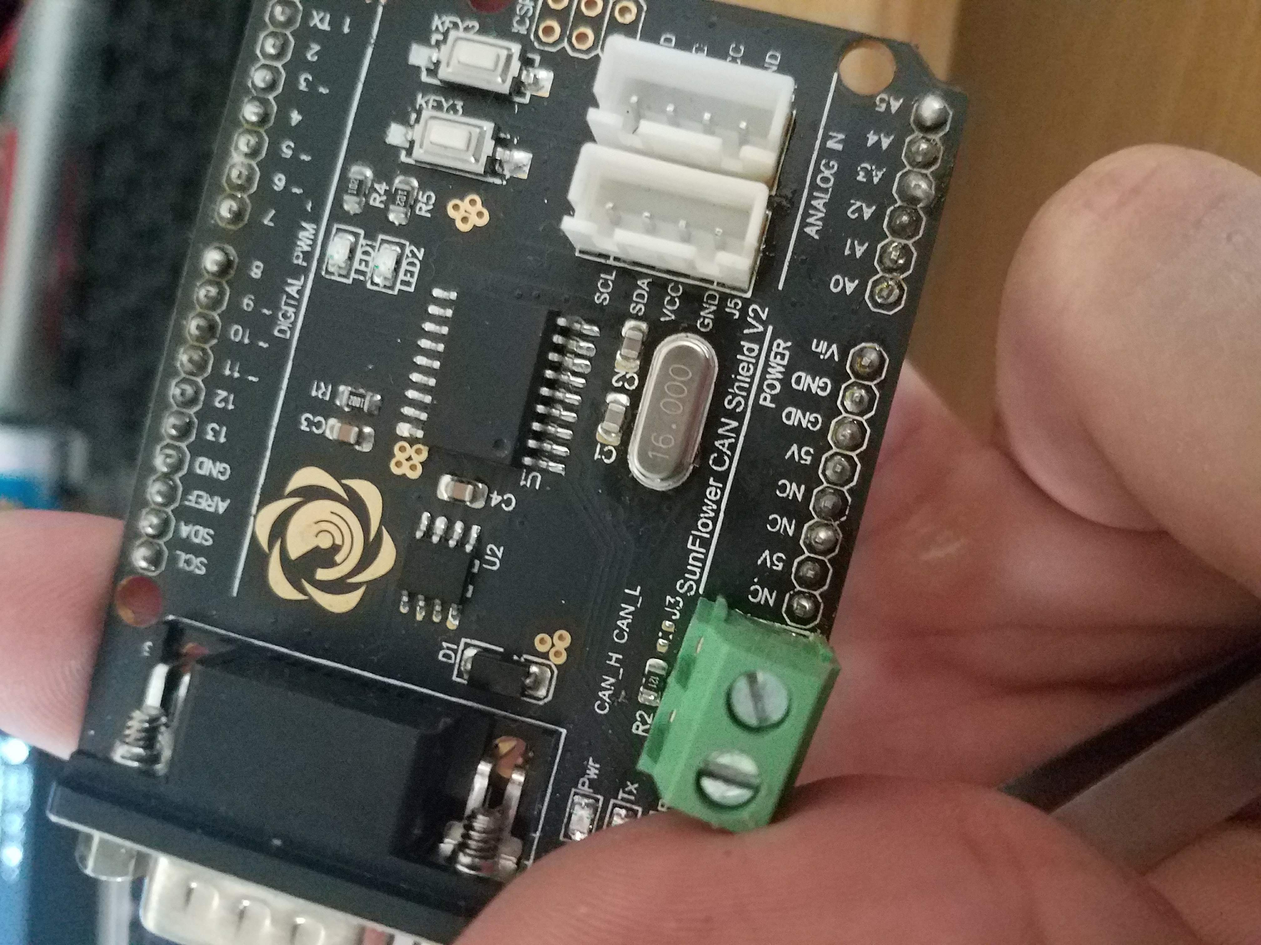
I soldered the headers onto the board since they come loose, I accidentally melted the plastic since I used a heat gun. I de-soldered the 8.000 MHz crystal and swapped it with a 16 MHz crystal since most of CAN libraries ideally use 16 MHz timing.

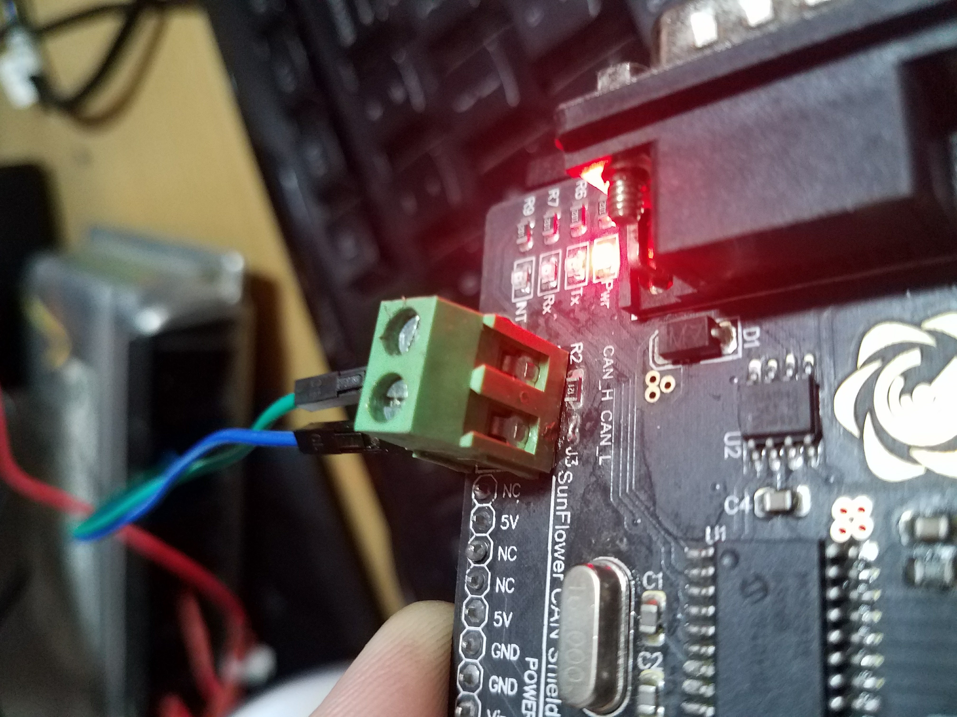
I also bridged the two exposed solder pads (in front of the green screw-down post, beneath the “CAN_L” letters) on the board to utilize the on-board 10 Ω resistor.
After doing all these you should be fine to use this shield on industrial/automotive applications for what ever you wish to accomplish.