
Eventually, this will also be posted on ms43wiki.com page, but for the sake of leaving personal comments, I’ve decided first to post it here first. Ever since I’ve been interested in converting my cluster from analog to digital, I’ve been thinking of the most obvious ways of pulling data off from the DME/ECU to display them digitally. We know that all cars have at least one type of OBDII standard communication, whether it is CAN, K-Line, L-Line, etc identifying the protocol is as easy as looking at the OBDII port on your vehicle and examining which pins are present. My BMW Z3 is running on a K-Line bus which I’ve confirmed on Torque as ISO9141-2 at 5 baud. Unfortunately, a shield supporting the K-Line protocol is not as popular as the CAN BUS protocol. Sparkfun has a shield that supports many OBDII protocols, including K-Line, but it sells at $50, which isn’t really convincing me at the moment. Although an economical K-Line shield isn’t available for the Arduino, making one using a L9637D is quite simple. The only issue is the software side which I suspect will require quite a bit of time to get the DME and the Arduino to communicate with one another if libraries for the L9637D don’t exist yet.
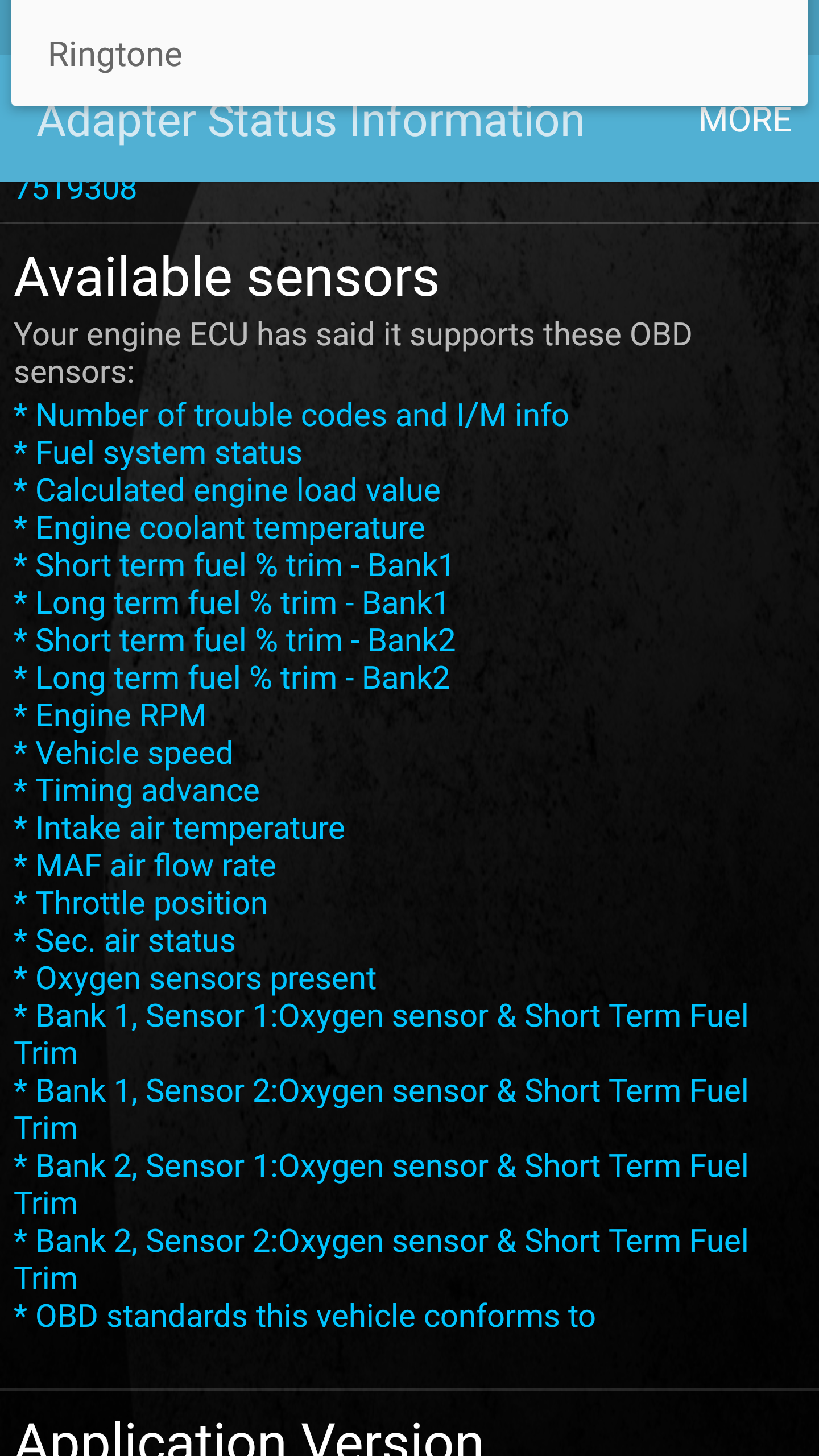
So, for this reason, I’ve stuck with trying to see which one node on the CAN BUS, let it be the DME, EGS/TCU, or IKE, is broadcasting the four essentials on a dashboard: Gas tank level, Speed, RPM, and Coolant Temperature. I know that the K-Line provides all four because Torque says so, but my question is: Does the CAN BUS support these?
Looking through the BMW Electrical Troubleshooting Manual, we find that there is indeed a CAN BUS.
.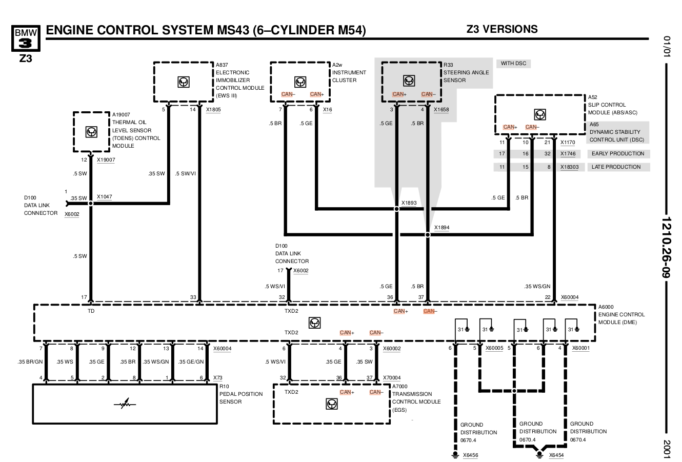
There are two CAN-BUS connections on the DME itself. One BUS connects to the transmission control module only, and another one connects to the “Instrument cluster, ABS/ASC/DSC control module, steering angle sensor,” as shown above.
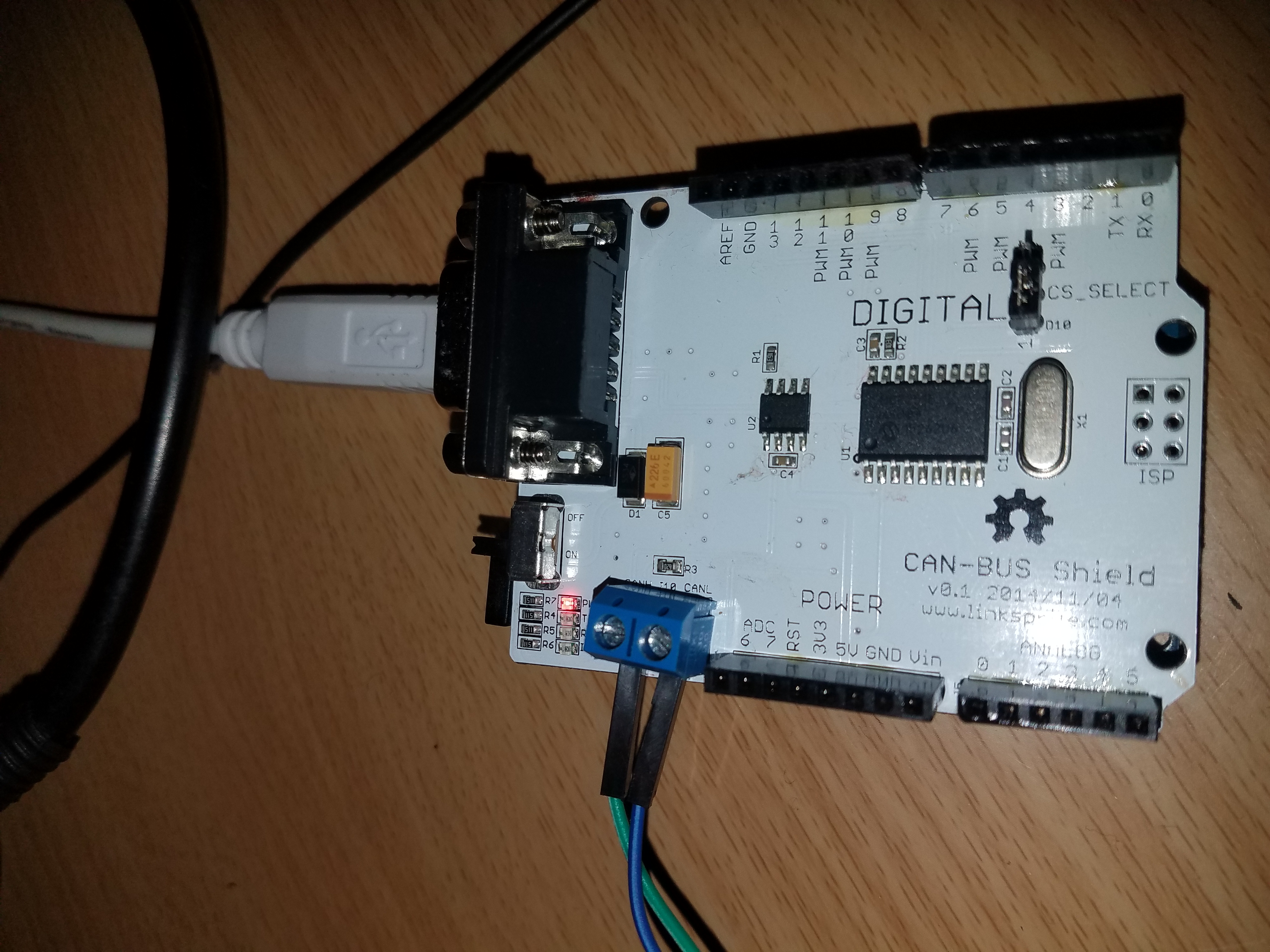
Im using a Linksprite CAN BUS shield which is working with coryjfowler’s MCP_CAN_lib CAN_recieve default example.
The jumper on the shield is connected so that CS_SELECT is bridged to D10. Also the baudrate from the arduino to the ECU is running at 500kbps as defaulted on the example.
The raw output: http://pastebin.com/qeWSLkmh
CAN-BUS Super Sniffer
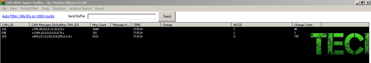
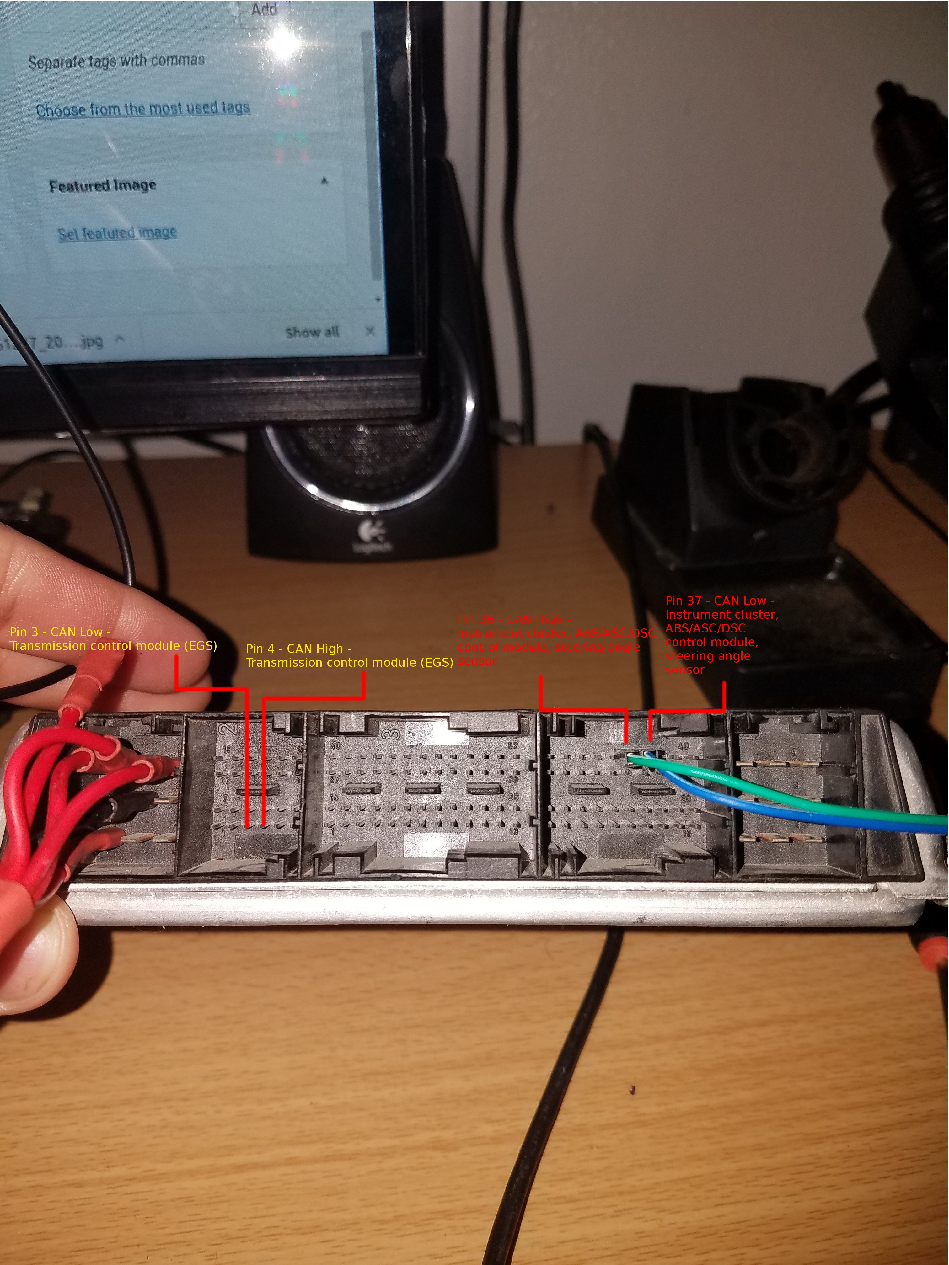
Connecting to the pins designated for the EGS (pins 3 and 4 on socket #2), you get the same data and the same CAN_IDs, suggesting that both CAN-BUS run on the same terminated twisted pair wires. Now it’s time to interpret this data and tap into the actual CAN BUS twisted pair wire on the car itself and collect data.
Furthermore, I can say it’s definitely worth taking a look at this: http://www.bimmerforums.com/forum/showthread.php?1887229-E46-Can-bus-project
CAN BUS DATA
Once you’ve got yourself hooked up on the CAN BUS, you can begin gathering data. What you decide to do with this data is entirely up to you. My purpose of tapping on this was already stated previously, I wish to display it digitally. Thaniel on bimmerforums.com has already done a tremendous amount of work interpreting data off of the E46 CAN BUS, so the majority of the formulas used on the E36 will be relatively similar to those on the E46. In the meantime, I’ve been gathering my own data and analyzing it to confirm the validity of Thaniel’s formulas on an E36. You can check out the data on my Google Drive of what I’ve been collecting, along with an Arduino sketch of what I used to grab the data. I’ve decided to ignore the specific data which is responsible for activating error lights, such as ABS, SRS, MIL, etc, as I will be using a different approach to determine their state. That method will be addressed further in a different article.
Furthermore, what you’ll find below is specific to my Z3 and possibly all other E36/7 series. I’ll be confirming Thaniel’s mins and maximum values for at least the four basic pieces of information displayed on a cluster: Fuel level, RPM, Odometer, Speed, and Coolant Temperature.
On a side note: All of my data is in decimal format. Should you decide to use decimal format for your data, you’ll have to take an extra step of converting to hex as most formulas require concatenating two hex values before converting it to decimal. I’ll be providing both formulas.
Fuel level
ARBID: 0x613 or 1555 in decimal
Formula:
For decimal values: N/A, Keep it as is. Much easier to understand for programming purposes.
For hex values: =HEX2DEC(B2)
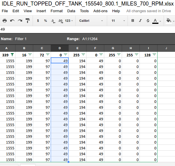
To test the fuel level reading, I’ve gathered many CAN BUS decimal values on the analog dial. I began by topping off my fuel tank at the gas station and driving back home to read the CAN BUS decimal value.

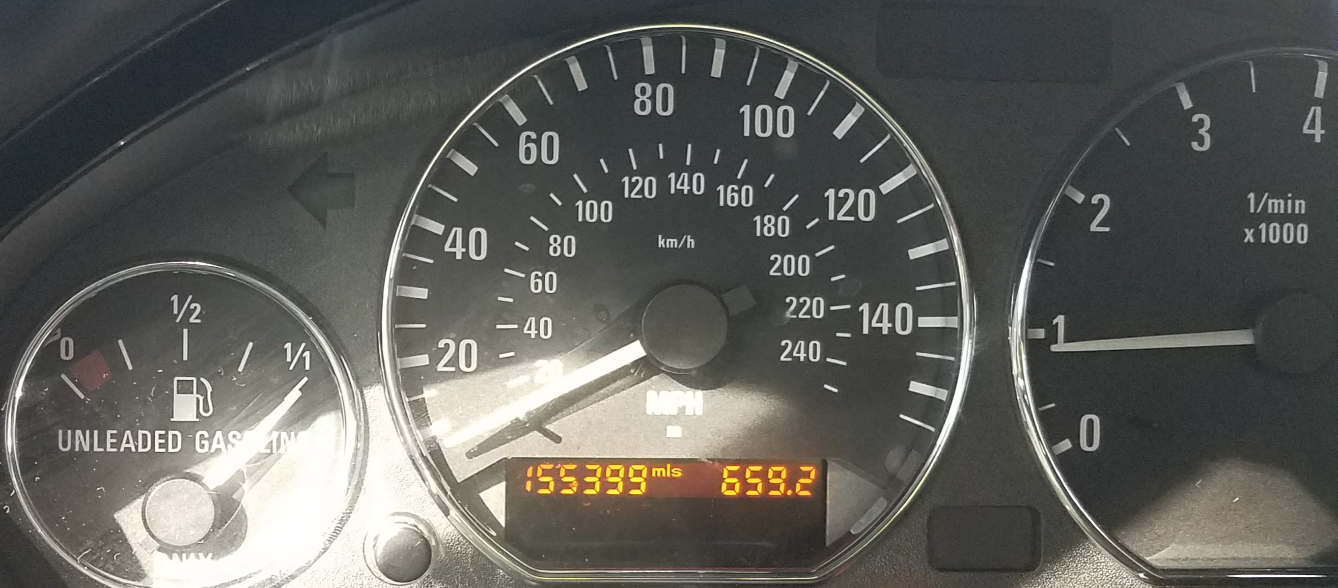
The decimal value on the CAN BUS was 49:
At exactly the 1/1 tick mark I got 47 in decimal:

At exactly 1/2 tick mark on the gauge, I got ~24 in decimal:
I’m waiting to get a 1/4 reading, but I can only imagine the value going down by a 1/4 factor. What I’m more interested in is confirming the value as the red light turns on. Even better when the tank is completely drained, which probably won’t happen.
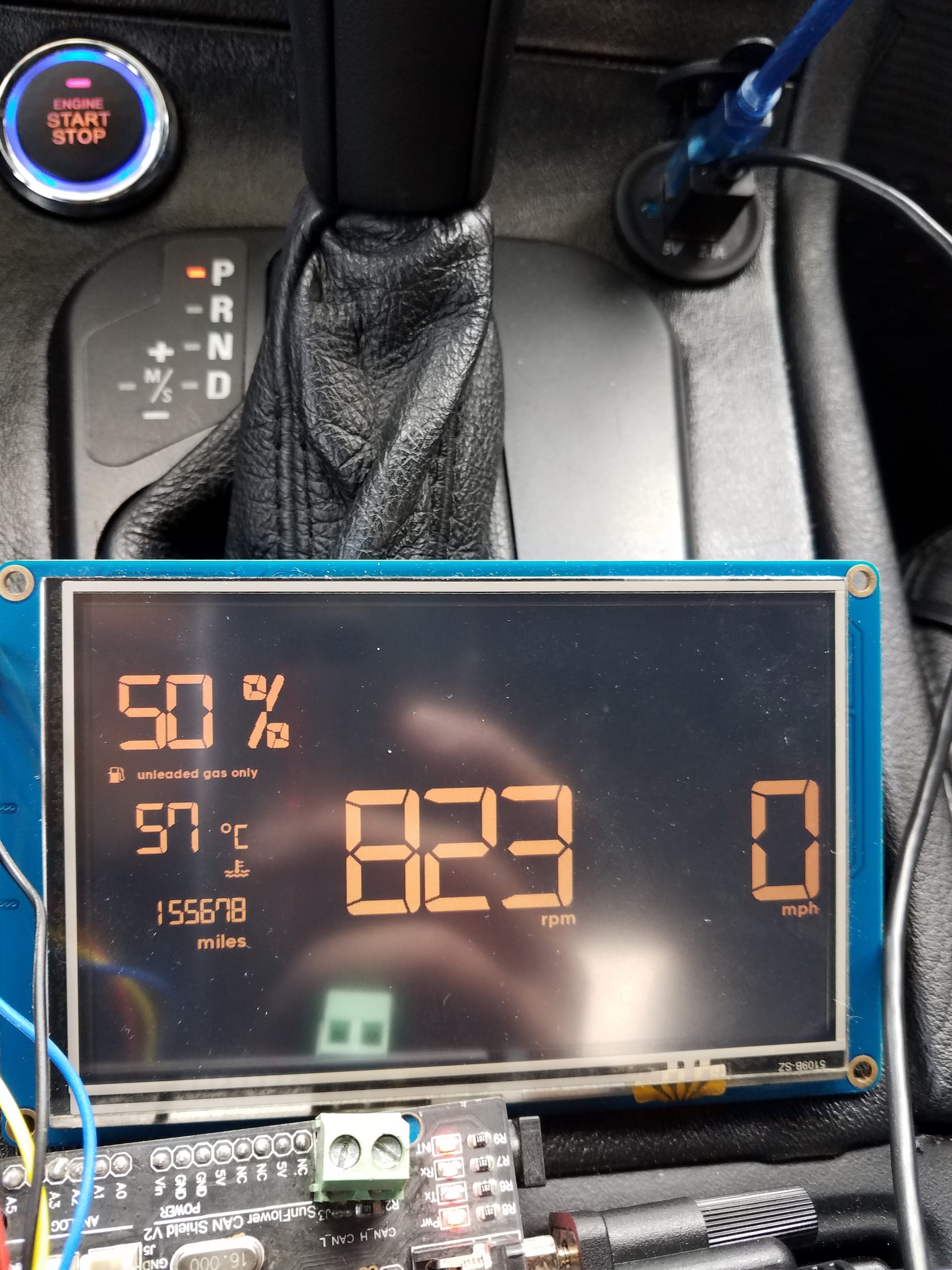
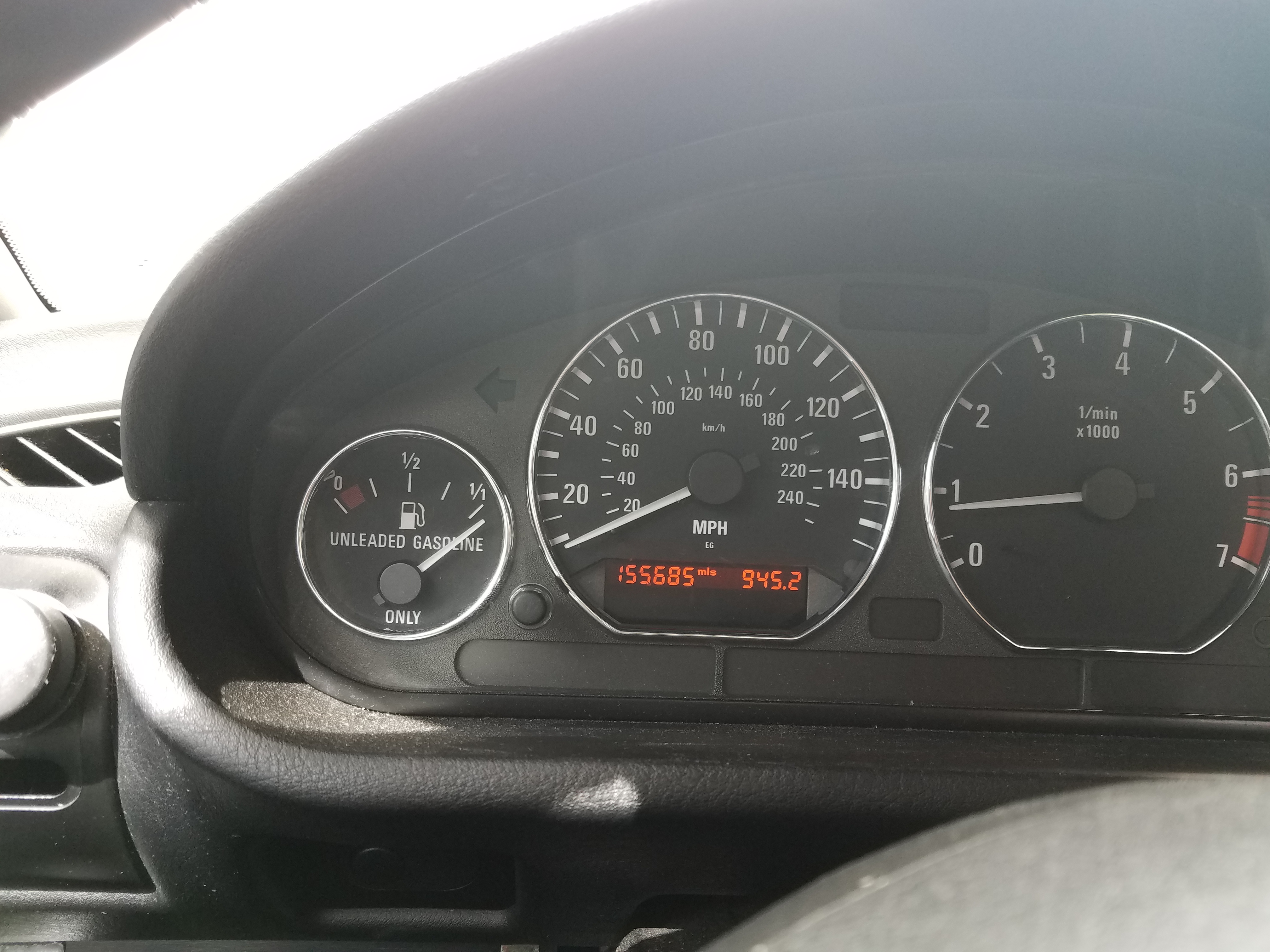
At the gas station, figured that the raw value would be higher than 50, but nope, with the gas tank completely filled, the value is at 50. Note: Ignore the %. I was initially going to display it as a percentage. What you see is the raw CAN BUS value.

Confirms Thaniel’s research. The fuel level goes from 50 to 8, then goes to 135 when the red low indicator turns on.
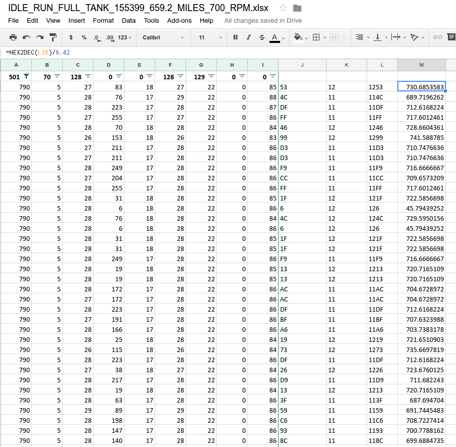
RPM
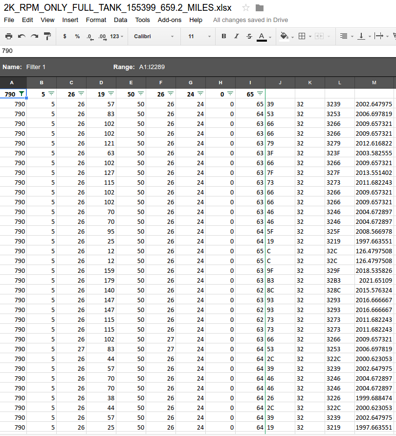
ARBID: 0x316, or 790 in decimal
Formula:
For decimal values: See below
For hex values: =CONCAT(B3,B2) and then =HEX2DEC(B3&B2)/6.42
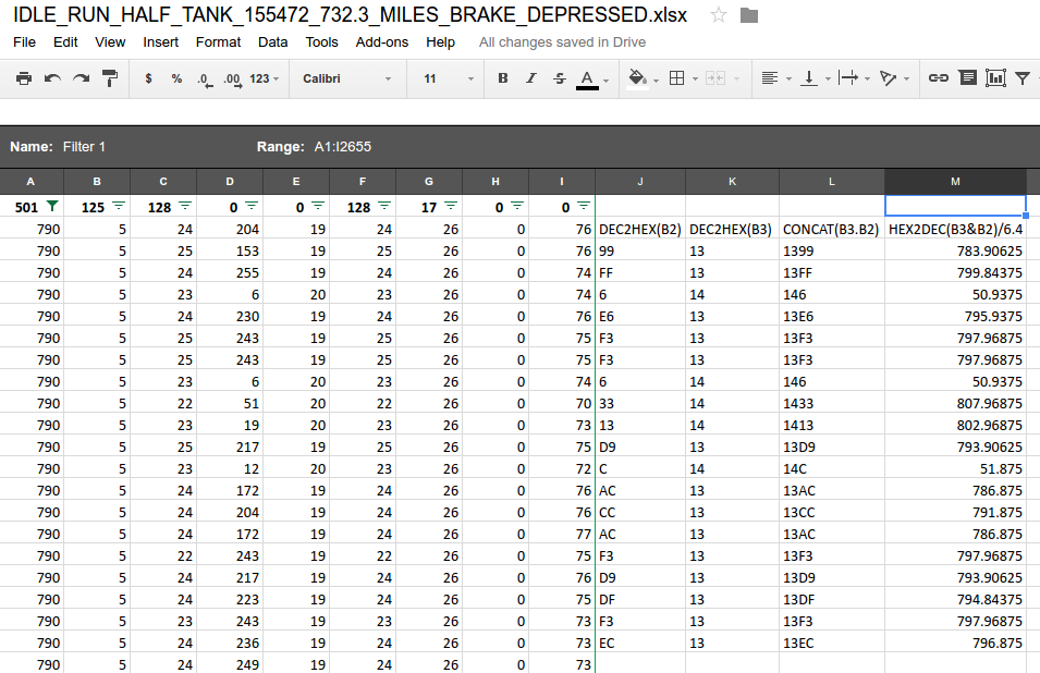
Rough idle, ~800 RPM. As you can see, there are three reading from 50-52 RPM, which is obviously incorrect. When programming to display the data, a reference will be used to discard faulty data, usually by comparing the last 2-3 calculated RPM readings.
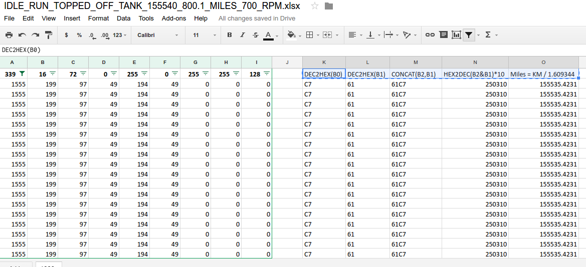
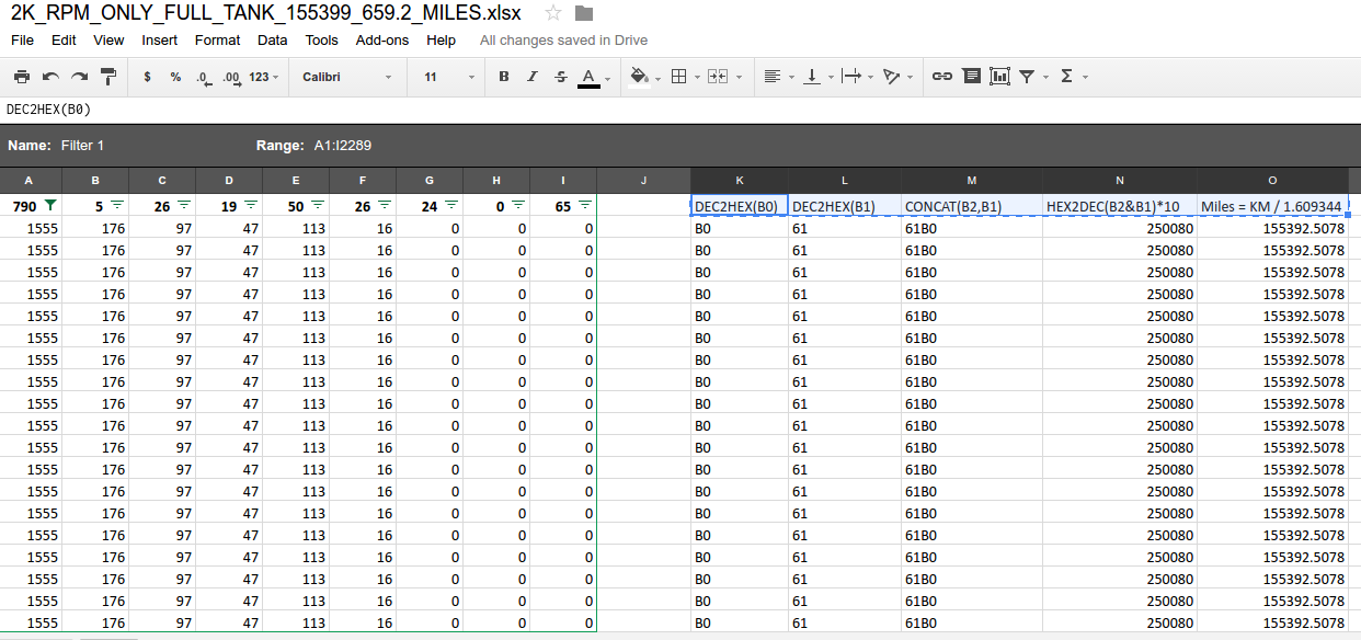
Odometer
ARBID: 0x613, or 1555 in decimal
Formula:
For decimal values: See below
For hex values: =CONCAT(B1,B0) and then =HEX2DEC(B0&B1) * 10 which will be KM
MILES = KM / 1.609344

Sorry for the typo, CONCAT(B2,B1) should be CONCAT(B1,B0) and HEX2DEC(B2&B1)*10 should be HEX2DEC(B1&B0)*10
Sorry for the typo, CONCAT(B2,B1) should be CONCAT(B1,B0) and HEX2DEC(B2&B1)*10 should be HEX2DEC(B1&B0)*10
Sorry for the typo, CONCAT(B2,B1) should be CONCAT(B1,B0) and HEX2DEC(B2&B1)*10 should be HEX2DEC(B1&B0)*10
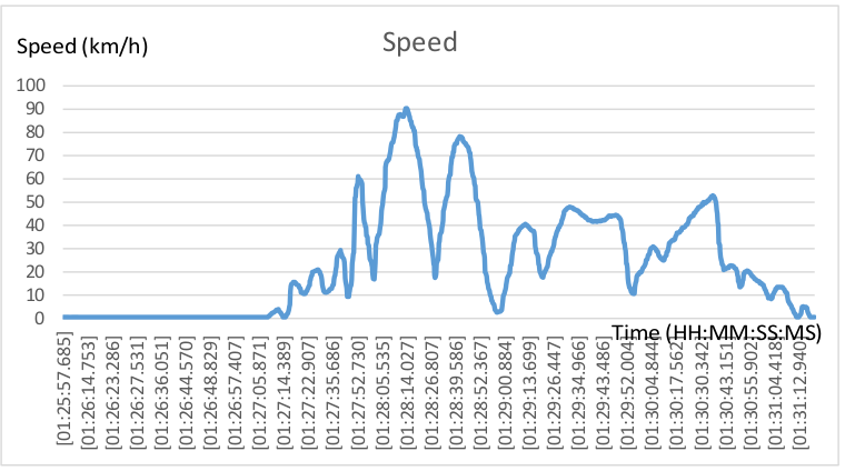
Speed
ARBID: 0x153, or 339 in decimal
Formula:
For decimal values: =(B2 * 256 + B1)/128
For hex values: =HEX2DEC(B1) then =HEX2DEC(B2) then =(B2 * 256 + B1)/128
Initially, I needed more data as it didn’t seem to match Thaniel’s formula. Thanks to Thaniel’s and beesquare’s formula, as of now, it seems acceptable. Although I wasn’t aware if I was indeed doing 90 mph, I am somewhat skeptical about this formula at the moment, but I will use it until we can compare the speed side by side. Below is my reading from a sample log which I decided to graph.
EDIT: I’m getting the impression that the units for this formula are km/h since I can only recall going up to ~60 mph, which is relatively close to about 90 km/h. More testing will have to be done.
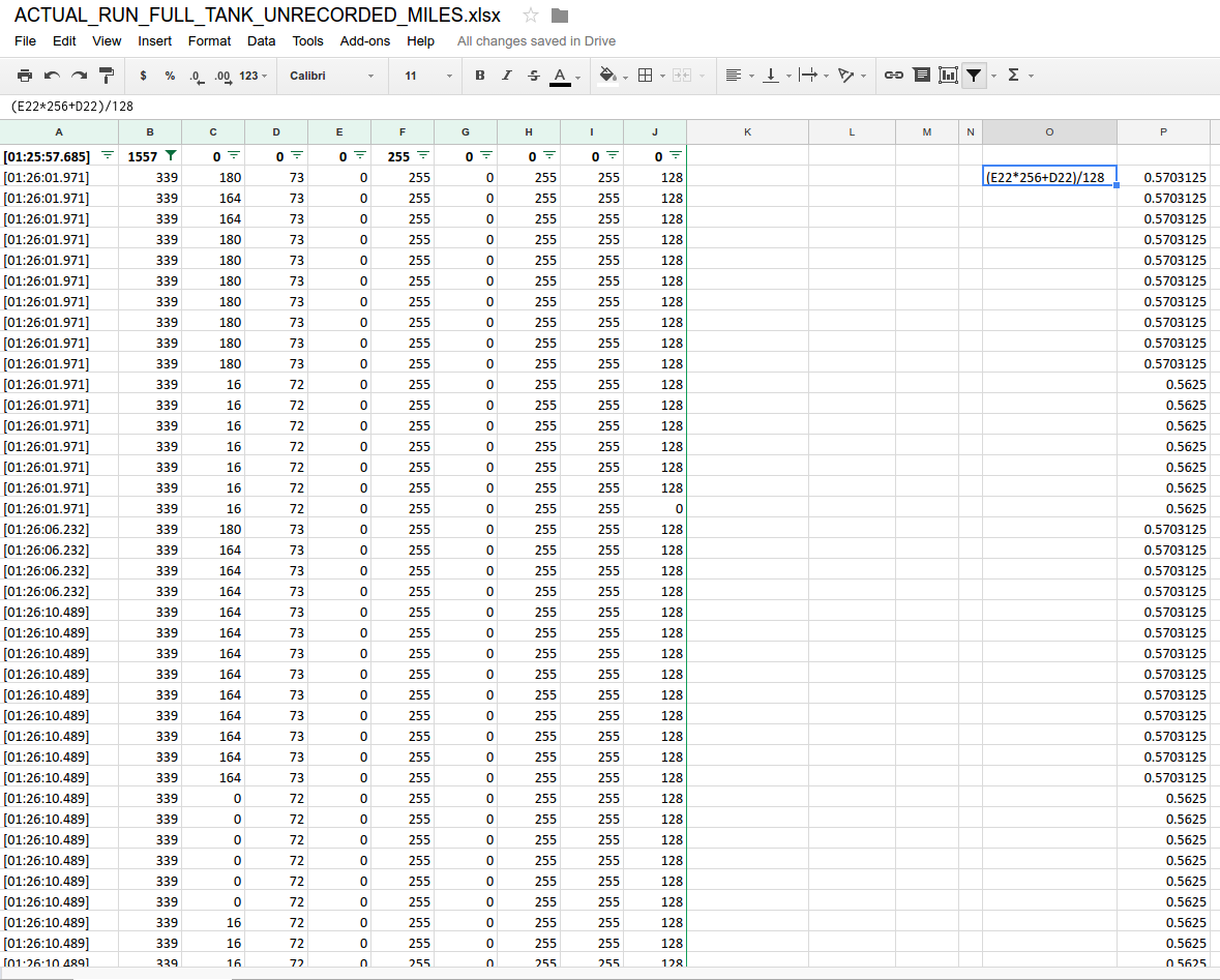
On the far right reads the speed. Since I was stationary at the moment, the reading is below 1mph/km. Which is rounded off to 0. I would have included all the data, but since it’s too many to include, I’ve decided to show the first couple.
Coolant Temperature
ARBID: 0x329, or 809 in decimal
Formula:
For decimal values: =.75 * B1 – 48.373 which will be degrees C
For hex values: =.75 * HEX2DEC(B1) – 48.373 which will be degrees C

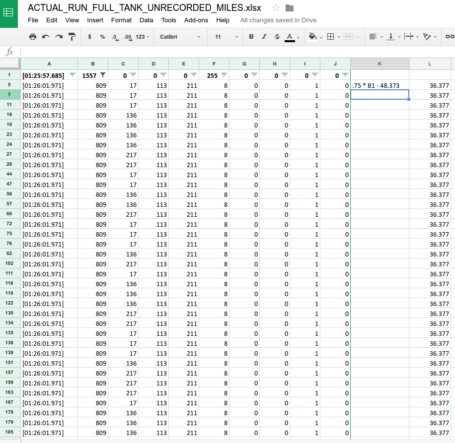
As I said earlier, for now, I’m only concerned about the common five readings. If I could, I will include more on the display since why not more information would be nice. My next step is writing an Arduino sketch to grab all five and display it on a display. More of this project is about to come in a different article.
Hello, this is some hard work you’ve done here, very cool!
I want to try tapping into my e36 can bus myself as I want to create a small screen similar to one I’ve found on the web (https://www.turbozentrum.de/CANchecked-MFD28-GEN-2-28-Display-BMW-E36-LHD_1).
Your findings will help me loads!
Although while reading I’ve found that your google drive that you have mentioned does not exist (err 404).
I have also found a small mistake in the article where you say “At exactly 1/2 tick mark on the gauge, I got ~24 in decimal”, but the screenshot underneath is the same as the screenshot posted earlier.
Glad I found this article and thank you for all the help! Will be waiting for your response. You are amazing.
-BisCut